

BENEFITS OF BUSHING MONITORING
When I reached out to Randy Cox at GE M&D to ask if they have any information on the topic of bushing monitoring, I expected to get a good piece, somewhat technical and always interesting. What we have here is much more than that with folks from GE, M&D, combined with a great case study from Alabama Power, a Southern Company company. That makes this piece far more than good; it makes it great. Articles like this is one of the things about our community that means the most to me; our willingness to share information that matters and that can advance the cause of transformer knowledge and understanding.
Introduction
As utilities move from traditional offline, routine testing of power transformer towards online continuous monitoring, many benefits are realized. Online monitoring enhances the safe, reliable operation of substation power equipment, measured performance, reduced failure rates and provides more consistent and frequent information of the existing fleet. In addition to these benefits the end user realizes improved integration of relevant information so that operations managers are better positioned to make more informed decisions. As a result of this, online monitoring affords utilities the ability to refocus resources in the form of O&M and capital expenditures, which leads to operating flexibility with improved reliability.
Eliminating, or at a minimum mitigating typical time-based maintenance/testing schedules via online monitoring and moving towards a more diagnostic driven maintenance program will allow for a more focused effort, as opposed to the typical time-based response of the past. After all, why work on something that doesn’t have a problem?
To perform offline power factor testing on bushings, the transformer must be removed from service, grounded, disconnected and then prepared for test. The bushings, transformer and typically the lightning arrestors are also tested during this downtime. On average, this takes a full eight-hour day with a minimum of two employees and often can include up to a total of four employees for this task.
The cost of this just for the labor can be as high as 32 hours, not to mention the cost of equipment in the form of tools, vehicles, etc. Monitoring the transformer via online dissolved gas and bushing monitoring will allow crews to find much better use of their time working to correct other, more pressing issues. The end goal is to reshape the current maintenance and testing programs of the utility’s substation equipment fleet with video, as opposed to pictures, so to speak.
A bushing monitoring system is an online system that continuously monitors the condition of the transformer bushings by monitoring the capacitance change of C1 and the relative power factor change (tan delta) of each bushing.
The Facts
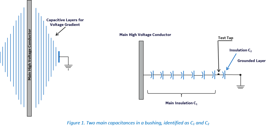
Oil impregnated condenser type bushings have a central conductor wound with alternating layers of paper insulation and conductive foil (known as condenser or capacitive layers). These capacitive layers are housed in a protective weather casing (typically porcelain) and filled with insulating oil. There are two main capacitances in a bushing, identified as C1 and C2 (Figure 1) [1]. C1 is the total capacitance between the center conductor and the test tap. Where the test tap is connected to the outer most capacitive layer, this is the point at which bushing measurements are made. C2 is the capacitance from the test tap to ground, where C2 is not part of the circuit during normal operation of the bushing.
The layers are designed to provide uniform voltage drops between each capacitive layer, effectively acting as a voltage divider. When a capacitive layer shorts, the voltage across each layer increases, increasing the leakage current proportionally. The magnitude of the current is a measure of the capacitance of the bushing, and a change of current magnitude indicates a change of capacitance of C1, which is an indication that the dielectric is not as efficient due to internal contamination of the insulation where the capacitive layers have been affected.
A bushing monitoring system is an online system that continuously monitors the condition of the transformer bushings by monitoring the capacitance change of C1 and the relative power factor change (tan delta) of each bushing. A system that has the ability to detect PD (partial discharge) activity generated in the transformer utilizing the same bushing adaptors (sensors) connected at the bushing tapping point, without any additional hardware mounted to the transformer, will provide further vital health information on the bushings and the transformer.
Bushing monitors should continuously measure the individual leakage currents of each of the bushings. A change in magnitude of the leakage current indicates a change of bushing capacitance. The change in bushing capacitance is then compared to the original nameplate capacitance to determine the bushing condition. The initial capacitance may be different from bushing to bushing. What is of interest is how much this capacitance has changed compared to when it was new.
Moisture is an enemy for bushing. Ingress of moisture into the bushing will deteriorate the bushing insulation, which will cause the dielectric losses to increase, driving an increase in the bushing dissipation factor (power factory; tan delta). Temperature and transients are also important factors that can also affect the bushing insulation, thus increasing the power factor.
Online relative power factor measurement has the timing differences among the three bushing leakage current phases, which translates to phase angle differences relative to each other. Since a change of phase delay equates to a change in power factor, we can determine for each bushing the relative (compared to the others) change of power factor as a percentage of the nameplate value.
Eliminating, or at a minimum mitigating typical time-based maintenance and testing schedules via online monitoring and moving towards a more diagnostic driven maintenance program will allow for a more focused effort, as opposed to the typical time-based response of the past. After all, why work on something that doesn’t have a problem?
Typical Requirements
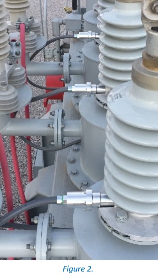
The installation of the bushing monitor requires information which can be found on the nameplate, in addition to the transformer’s operating voltage. This information consists of the mechanical aspect of the bushing tapping point, where the bushing monitor adaptor will be inserted. This is to ensure a secured installation and uncompromised contact with the test tap (Figure 2).
With an expanded library of bushing types, the bushing model will generally suffice. However, the availability of drawings, which include the flange, can be beneficial. The electrical characteristics, such as the % power factor (tan delta) and C1 capacitance values located on the nameplate are used to configure the bushing system.
The nameplate values also serve as the starting point of the bushing’s life, in terms of its capacitance and relative % power factor change. In short, the mechanical and electrical parameters of a bushing are the key elements for a successful installation of a bushing monitor.
Success Story
Southern Power, a subsidiary of Southern Company, is a leading wholesale energy provider that operates 49 generating facilities with more than 11,200 megawatts of electricity generating capacity all over the USA.
Their 102-megawatt Henrietta Solar Project in Kings County, California, USA, achieved commercial operation in October 2016. Southern Power had the foresight to install a bushing monitoring system from GE to monitor a key 50 MVA transformer.
The Problem
On 26 March 2019, the data being received from the bushing monitor through the SCADA system showed an alarm coming from the phase B bushing on the LV secondary side. It was indicating an increase of the relative percent change in Power Factor (PF) from 311% on February 27th to above 895% on March 26th, 2019.
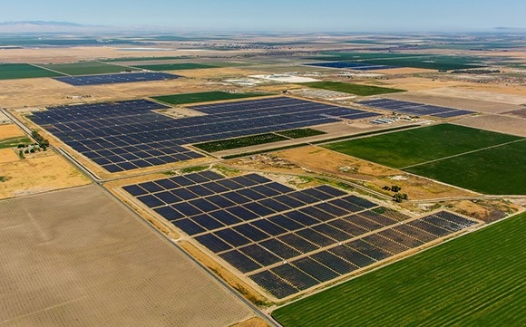
Henrietta Solar Farm (Photo: Southern Company)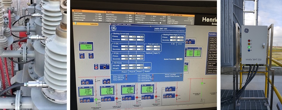
Figure 3. Bushing adapters (left); screenshot of SCADA screen (centre); picture of the bushing monitor (right)
Analysis
Figure 4 compares the primary and secondary polar plots for the relative percent Power Factor change. The data on the Primary side does not show any abnormal behaviour. Although the data points are not tightly packed together, they are in the same region and within normal range.
Compare this to the secondary side where the data clearly shows a very large and significant increase in the %PF generated by the phase B bushing. This increase in %PF started in February 2019.
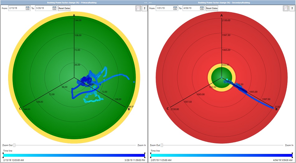
Figure 4. Polar Plots showing Relative % Change of Power Factor
Figure 5 below shows the polar plots for the primary and secondary bushing with respect to the % change in Capacitance C1. The data points on the left polar plot from the primary side are neatly packed and stable which is expected in normal operation.
However, on the right polar plot for the secondary side, data points show a change of ~1.5% on phase A, but the concerning element is the progression for phase B which reaches 4.2% on March 28th, 2019.

Figure 5. Polar Plots showing % Change of Capacitance C1
Online bushing monitoring affords utilities the ability to refocus resources in the form of O&M and capital expenditures, which leads to operating flexibility with improved reliability.
Based on the data from the bushing monitor, Southern Power decided to take the transformer offline to avoid a possible catastrophic failure of the bushing. They replaced the suspicious bushing and returned the transformer to service.
Subsequent offline tests on the suspicious bushing confirmed that the bushing had indeed significantly deteriorated from its original values and that the operational decision taken had been correct.
The bushing monitor had correctly highlighted that the Power Factor of that bushing was starting to change at a fast rate in the last month and that a precautionary replacement should take place whenever possible.

Neil Hutchins
Neil Hutchins has over 21 years of experience in transmission/substation maintenance. Neil is the Supervisor of the Southern Company Services, T&PS Equipment Services Group, which provides support to Southern Company OpCos and affiliates on major equipment. He is also the Chair of the Southern Company Major Equipment Committee and a Member of Southern Company Breaker and Substation Maintenance Committees. Neil is an IEEE Senior Member, Member of IEEE/PES Switchgear Committee and a Member of IEEE Alternative Gases to SF6 Task Force and Working Group. He is also a Past Member EPRI Substation Task Force.

Elm Costa
Elm Costa is a Sr Lead Electrical Engineer within the GE Renewable Energy group, and currently is and has been the Technical Lead for several NPI projects. He is the subject matter expert on on-line bushing monitoring, partial discharge and transformer models. Elm obtained his bachelor's degree in physics from the Universitat de Barcelona, and a PhD in physics at the Queen’s University, Belfast. After several years working as a Research Fellow at QUB, he moved to Andor Technologies Ltd. In January 2008 he joined Kelman Ltd (later acquired by GE) working in the field of high voltage asset monitoring using electrical signals, and later specialised in capacitive bushing and partial discharge monitoring.

Kwasi Yeboah
Kwasi Yeboah has been with the GE Monitoring and Diagnostics business for the last 14 years supporting customers in various roles while based in Montreal, Canada. He holds a BSc in Mechanical Engineering and certificate in Management and Quality Assurance, both from École de Technologie Supérieure. Kwasi is also a Six Sigma Green Belt certified and RCA Leader.